Using Micro-Controller to control Bulb through Relay
This Project we are going to use Micro-Controller to turn on/off the bulb through Relay. Through Relay we use Micro Controller as a signal transmitter to give a signal to the relay to turn on and off relay through that we able to turn on and off the 220v bulb. In this project, Micro-Controller gives a signal to the Transistor (2n2222 or BC547) to turn on/off the relay. So the Schematic isn't so different from the last project that we do.


The Component that we're going to need are:


- One Relay 5v (x1)
- LED (Red, Blue, Green,..., x1)
- Resistor 220R (x1)
- Resistor 1K (x1)
- Resistor 10K (x1)
- Diode 1N4007 (x1)
- Transistor 2n2222 (x1)
- T-block 3Pins (x2)
- PCB board
- Acid
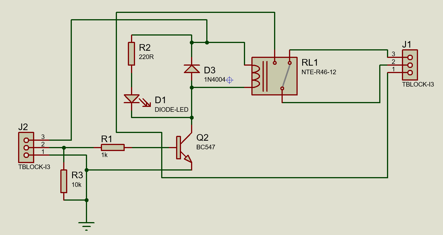
Just like before we draw Schematic and PCB in Proteus and afterward we print Layout just like the last project but in this Relay we need to connect the transistor to the power so that we can transmit the signal from the micro-controller to the relay.
- The power (5v) that we receive from the micro-controller needs to pass through 1K resistor to the Base pin of the transistor just like in the picture below.
- We put the 10K resistor before the 1K resistor to prevent unnecessary currents that still lurking in the schematic from destroying all our circuit so we make it go to the ground just like the picture.Schematic
 We connect the Collector pins of the transistor to one of the relay power pins. And the emitter pin to the ground just likes in the picture.PCB
 After we finish in making the relay like (Ironing, Drilling hole, Adding Component and Soldering) all we need to do is connect the power to the relay.

We move on to the Testing Process:
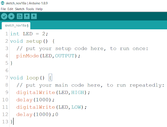
- In this case, I use Arduino as a microcontroller to control the relay. So I code the Arduino to blink on and off with delay 1 second each. After that, we upload the code to the Arduino.
- Then we connect 5v from Arduino to the one of the Pin-Header (VCC), GND from Arduino to one other of the Pin-Header and Pin Number or Signal (In this case pin 4 from Arduino) to the Pin-Header that connected to the Transistor. Just like in the picture. (Note: You must remember which Pin-Header is VCC, GND, and Signal so that you don't confuse).
- We connect our bulb wire (L) to the T-block pin (COM) and the other bulb wire (N) to the other T-block pin (N.O) and then we plug the bulb to the AC 220v socket.
- So when the Arduino sends the signal to the transistor the relay will turn on or off just like the code that we write and the bulb should be blinking the same as we coded the microcontroller.


Here is my email if you have any question: motitakoy@gmail.com


0 comments:
Post a Comment